Building an Arc Reactor
§Why?
Because I thought it'd be cool. I'd been working on building a functional version of Chua's Circuit as an experiment into generating randomness from chaotic systems (hope to write that up sometime), and had some time left over (okay not really) to build a case. Iron Man being one of my all-time comfort movie, it seemed like a good fit.
§Step 1: The Model
First part involved getting a good model of an arc reactor. I usually prefer YouMagine as an Ultimaker user and fan - and the models are usually of a higher quality - but having found none that worked, I turned to the much more popular and much bigger Thingiverse. Clearly the designs for an arc reactor should be easy to find. However, it took a lot of looking. Most models are designed to be worn on the chest - which is fine until you realize they're meant for people without arc-reactor sized cavities in their sterna. Most are simply a ring of LEDs with the right shadows to make them look like Arc Reactors. Pfft.
After much looking, I landed on this. Good design, separate parts for printing in separate colors (for those of us without dual extruders), and seems easy to put together. I should've been watching out for a few more features, as I discovered later. The TL;DR there includes a spot for cable management, easier snap-on fittings as opposed to hot glue, and better structure that reduces the need for supports. Not knowing any of this, I soldiered on with the one I had.
§Step 2: Printing
Surprisingly, printing was the easiest part of this build.
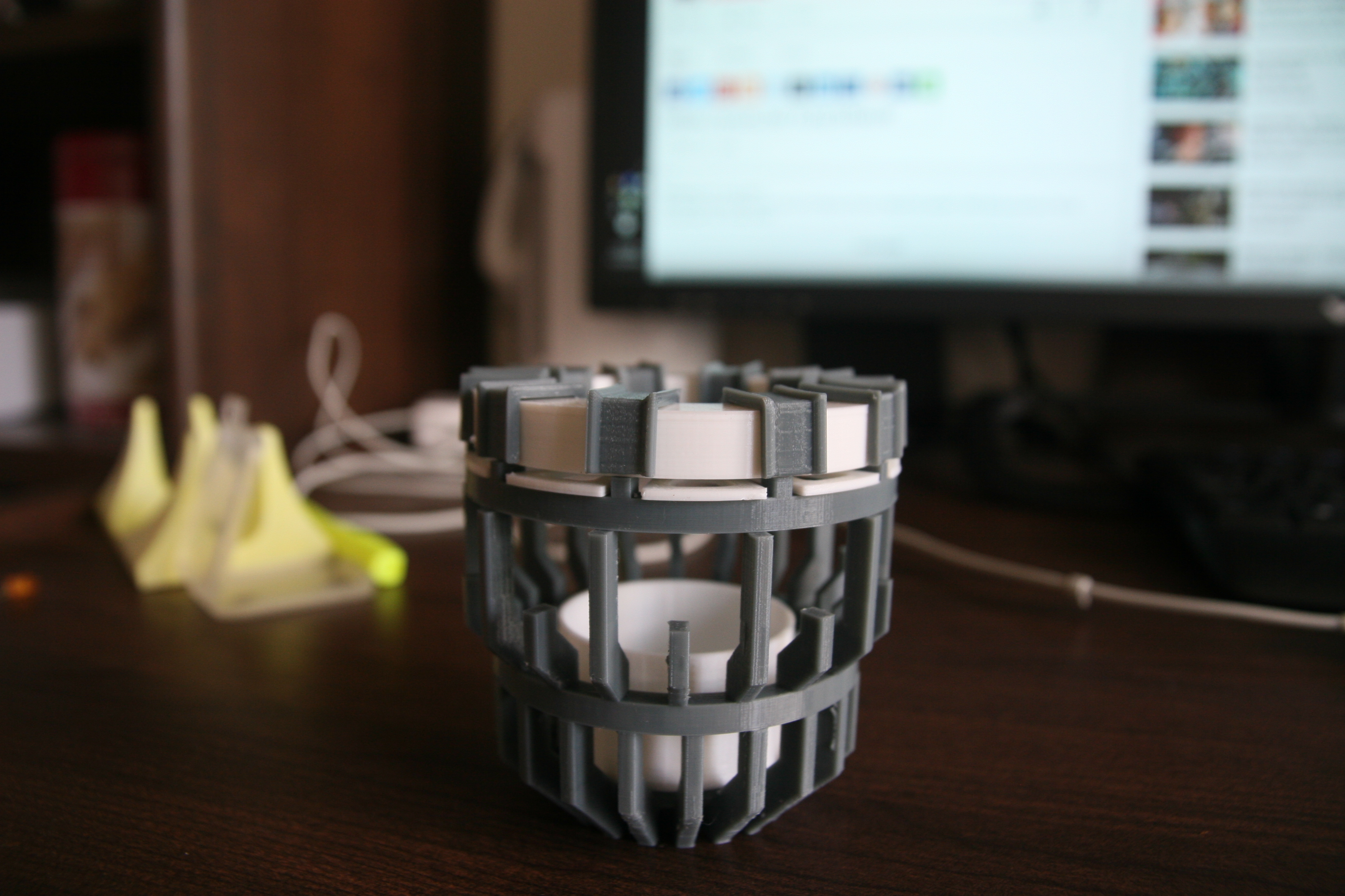
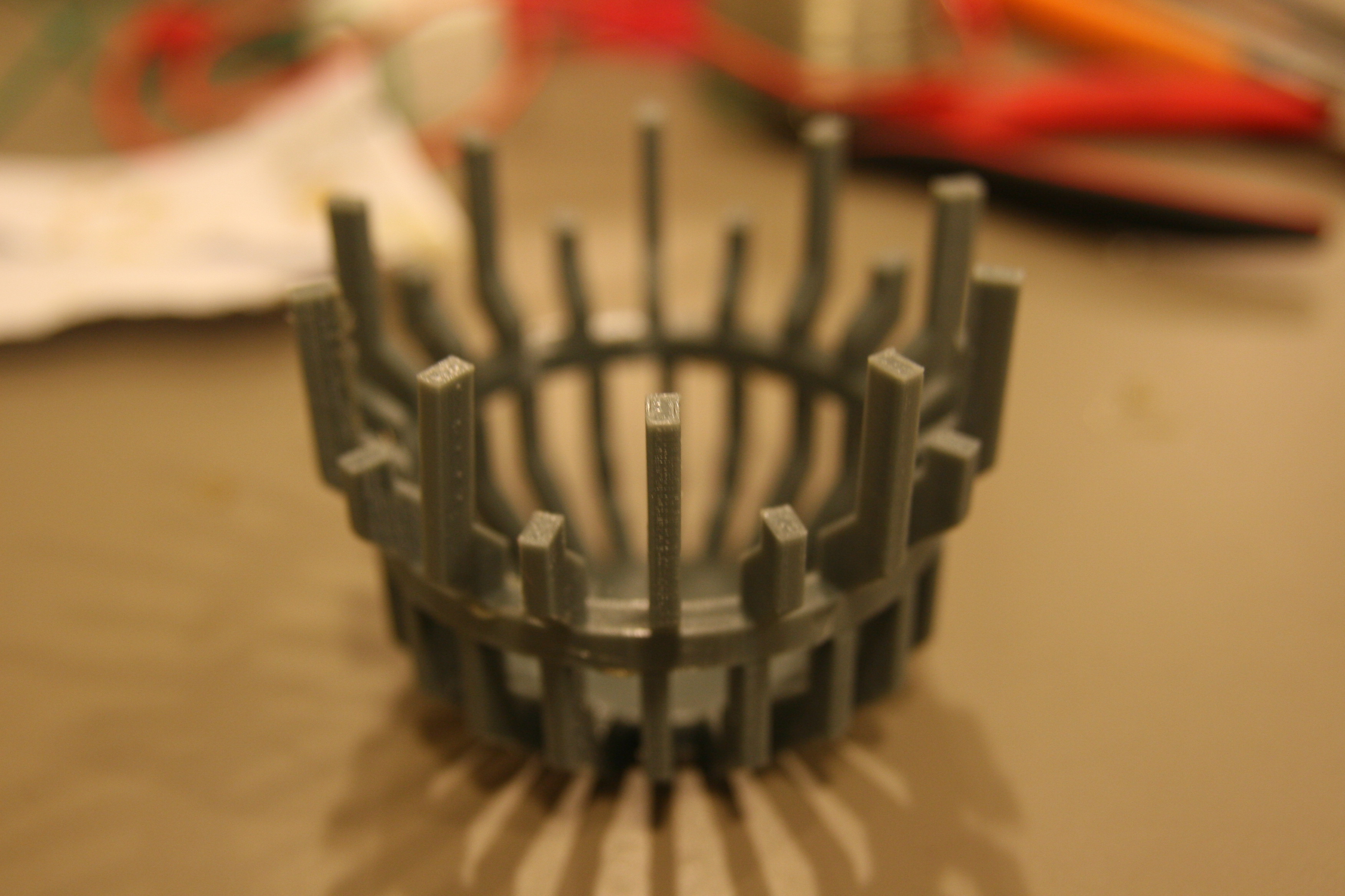
Above you can see the parts assembled. I chose to print the diffusers out of white PLA, and the rest out of grey. It was suggested that the lower parts be printed out of gold-ish filament, but a few attempts did not look as good as expected. They ended up being gray, with the promise of being spray-painted gold "soon".
A number of pieces fell apart in the process of removing supports, perhaps it was better to print out of ABS - unfortunately I did not have any on hand. Rookie mistake.
Once they were satisfactorily printed to assemble, the next part involved - assembly.
§Step 3: Wires
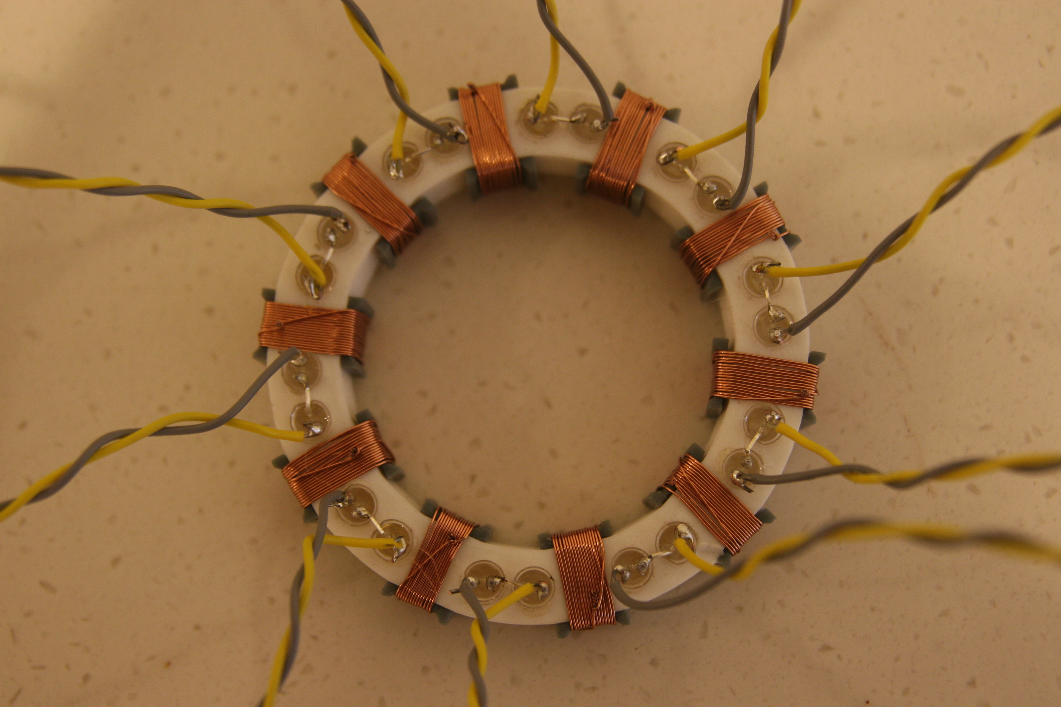
I'm not sure how Tony Stark built this in a cave, but I was definitely working with a box of scraps. Found some old coiling wire in the lab, and after trying some of the smaller variants, a bigger 1 mm wire turned out to be perfect. I needed one that gave was solderable, easy to coil while maintaining shape afterward, and aesthetically pleasing.
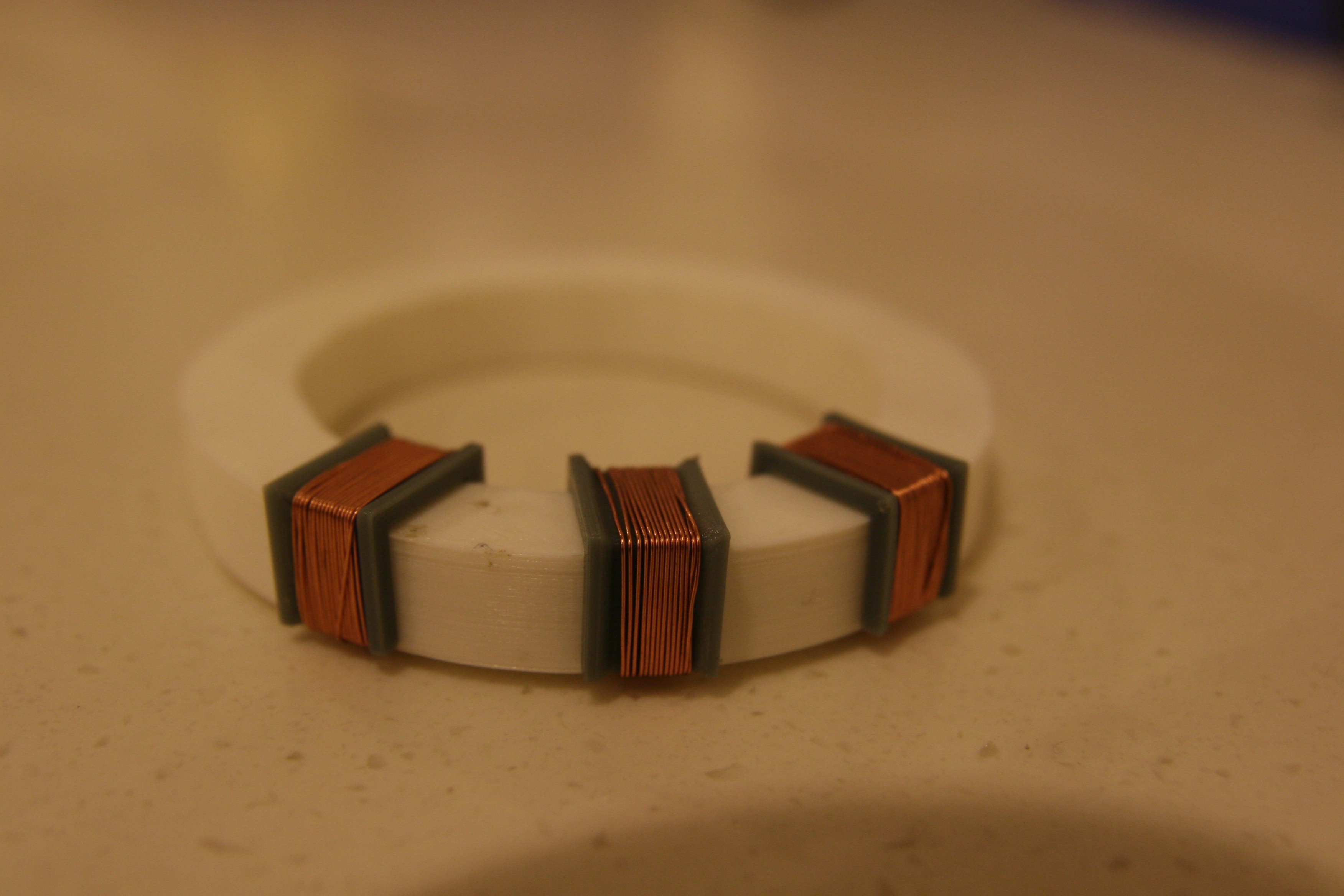
Coiling was quite fun - almost therapeutic. Getting all of them done did take a while, espeically since it included burning off the ends of the coil and soldering them together without leaving any slack. It proved difficult to place and solidify solder joints under tension, and the joints eventually cracked under the stress. Not their mistake, mine. The final solution ended with me twisting the ends together with needle-nosed pliers, snipping off the end and preventing any unravelling with a blob of - solder.
Once this was done, the next part involved adding the LEDs. A quick test was performed to make sure the diffuser did not have any imperfections, and then it was stright to gluing LEDs. Anyone attempting the same should remember to align the anodes and cathodes the same way around the ring, as snipping off the wires makes it near impossible to tell without testing. Besides, arranging them properly leads to better wiring patterns (we'll see).
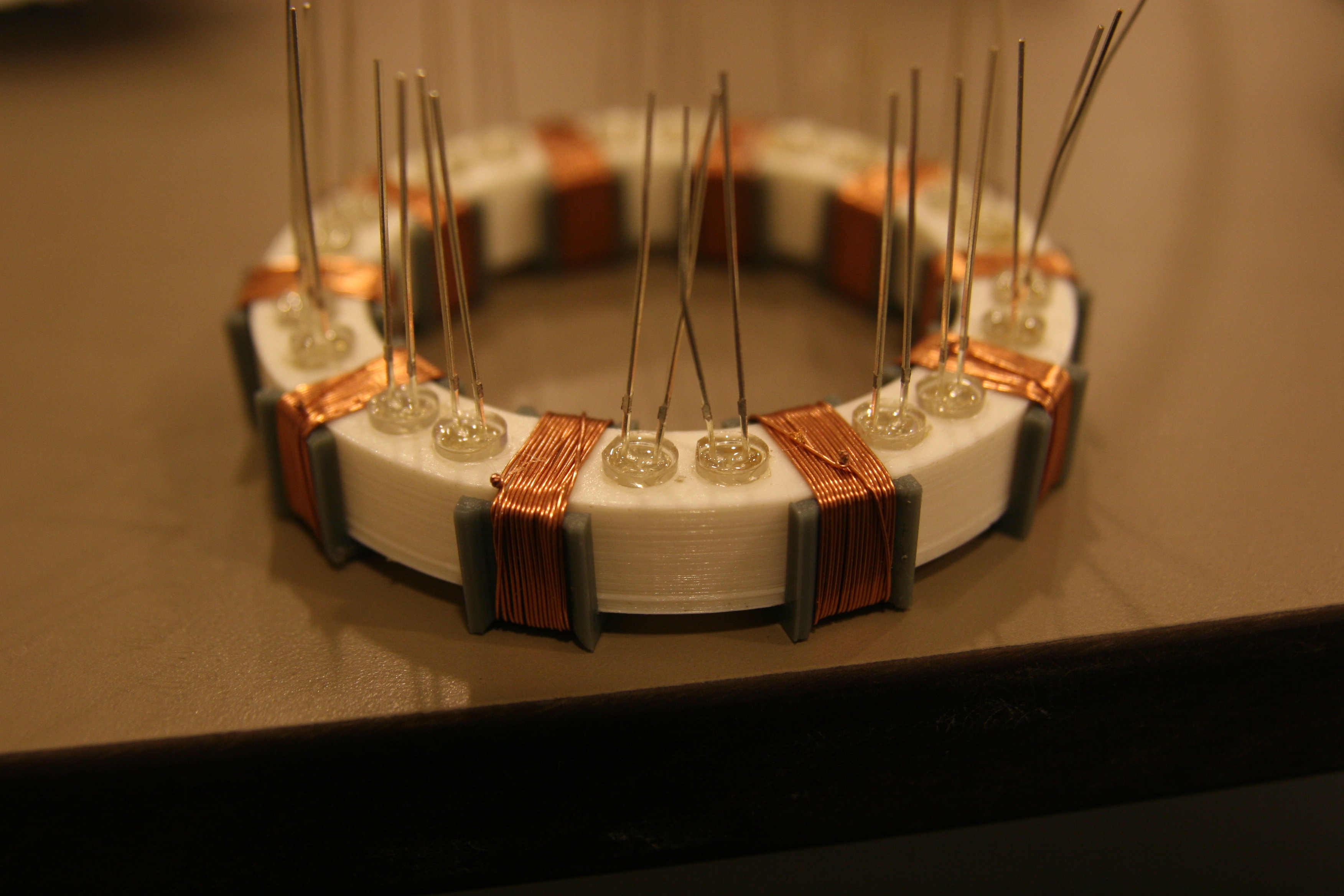
My wiring plan included the use of a 5 volt supply, hence the paired up LEDs (eliminated the need for resistors, if you ask me [not really though]). Hot glue is a good idea, as it doesn't blemish the light and improves diffusion. Next part involved testing the LEDs individually before any wiring was done -
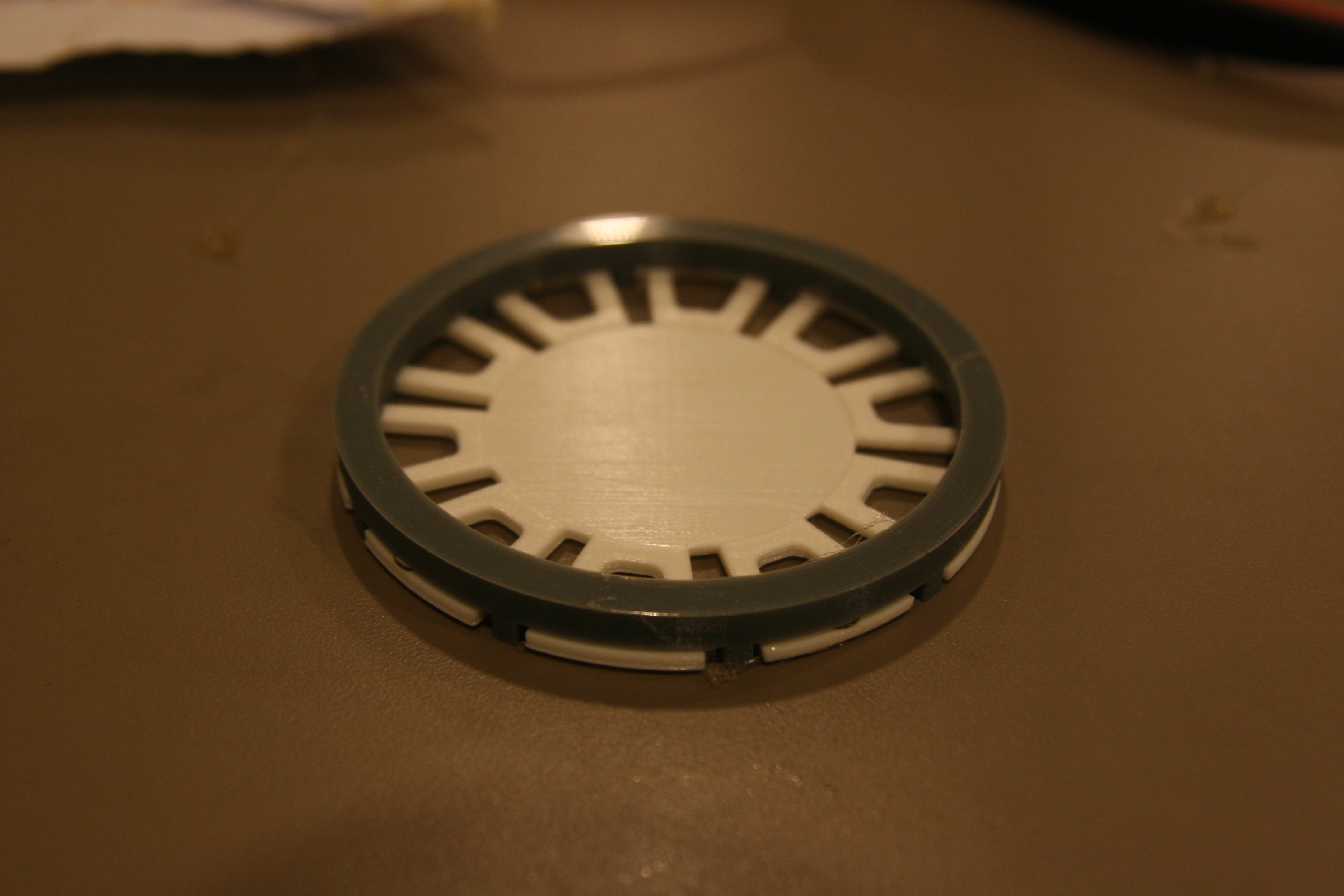
The diffuser - print with low infill and a diamond pattern - along with the glue turned out nicely.
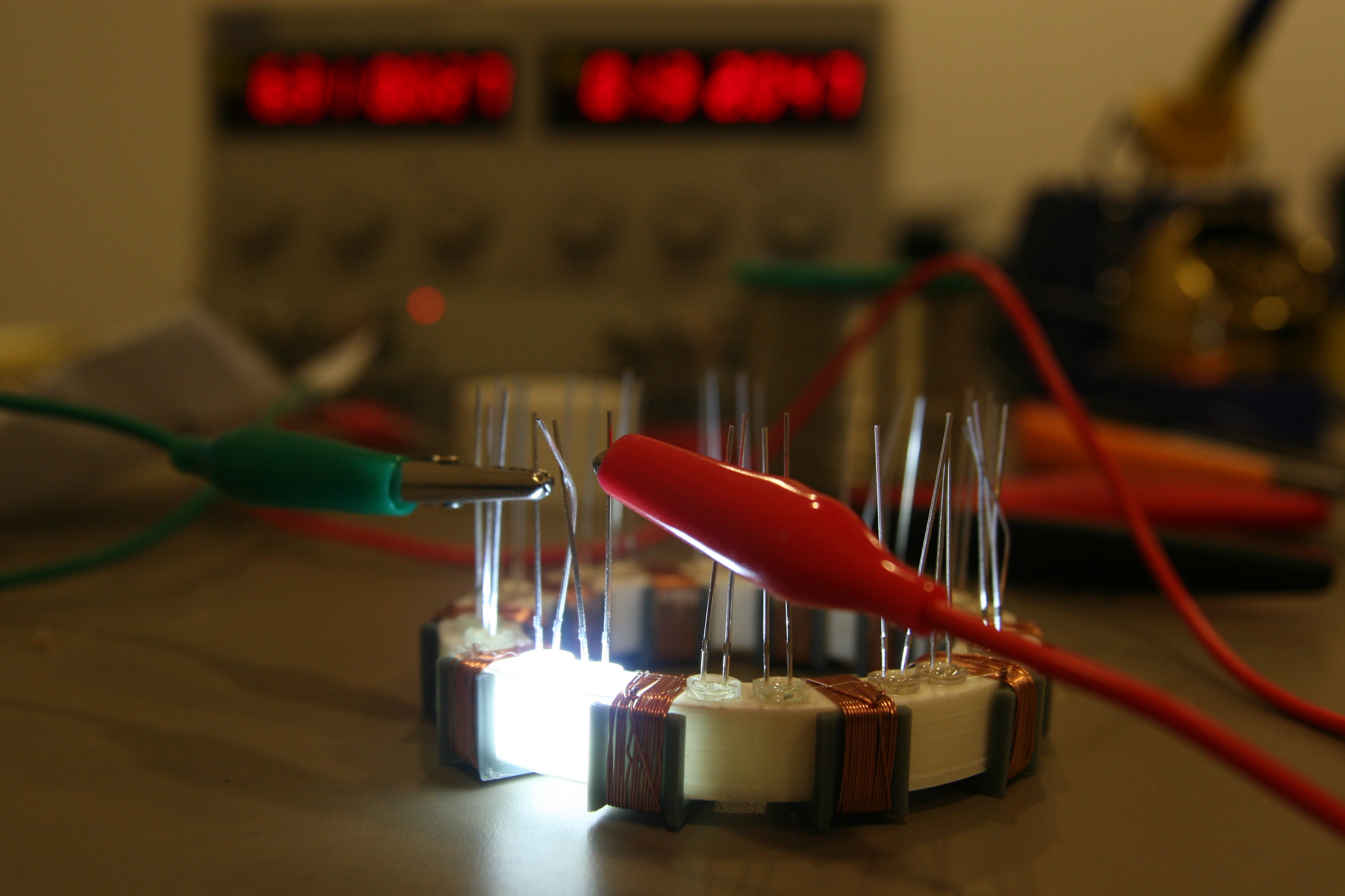
Now came the hard part. In order to sit the housing as flush as possible to the casing, I had to solder right next to the base of lights, and attempt to short adjacent leads together using functionally strong solder joints (I guess I didn't learn). If you're familiar with old lights in a box, you'll know they break at the base with any tension at all, leaving a tiny exposed strip of metal that will not respond to solder.
Thankfully all the joints were completed under much pressure, and a few quick tugs did not reveal any issues (always tug your solder joints!).
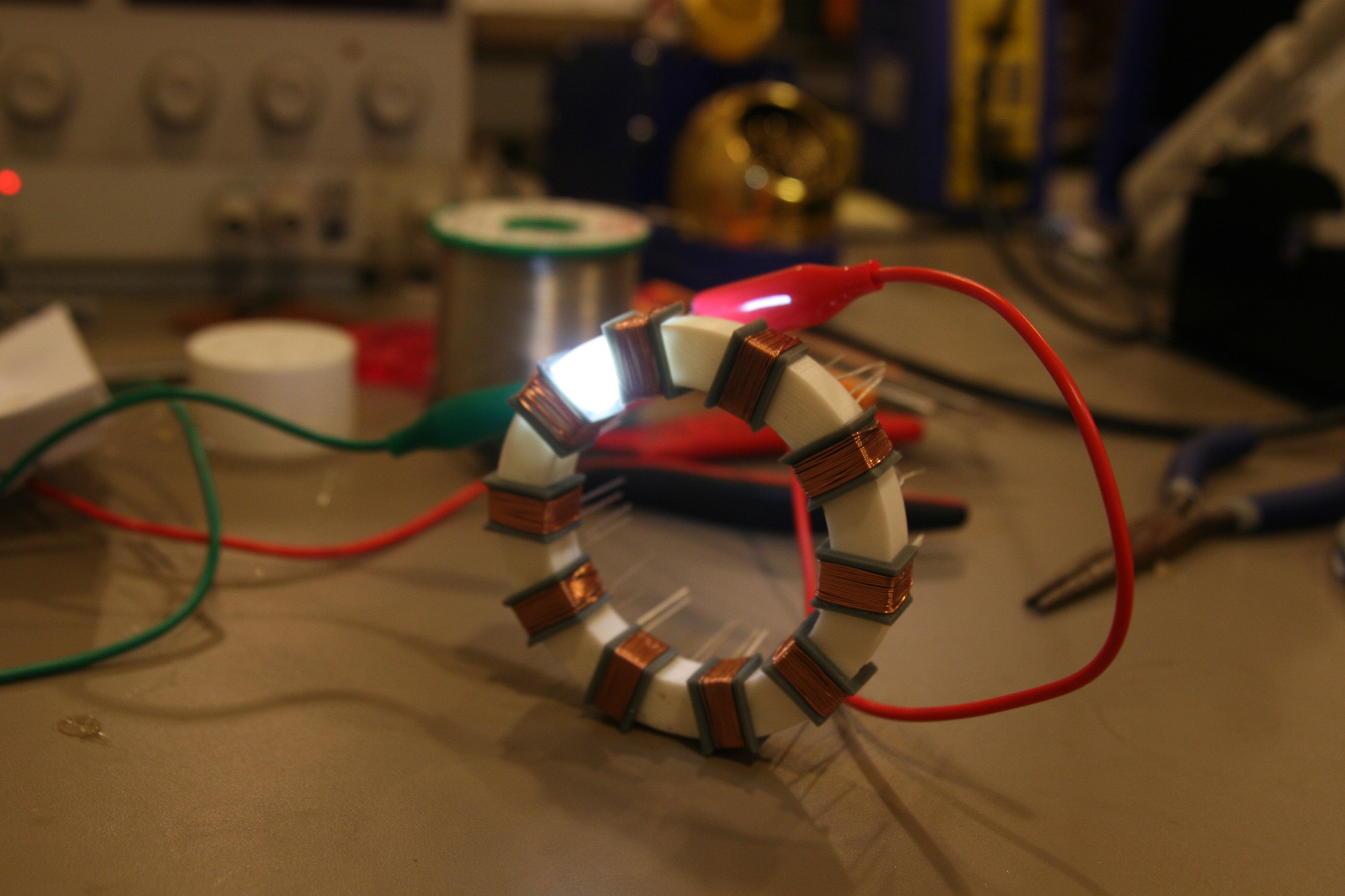
Now came the time to install the first backplate and POST. No problems here….
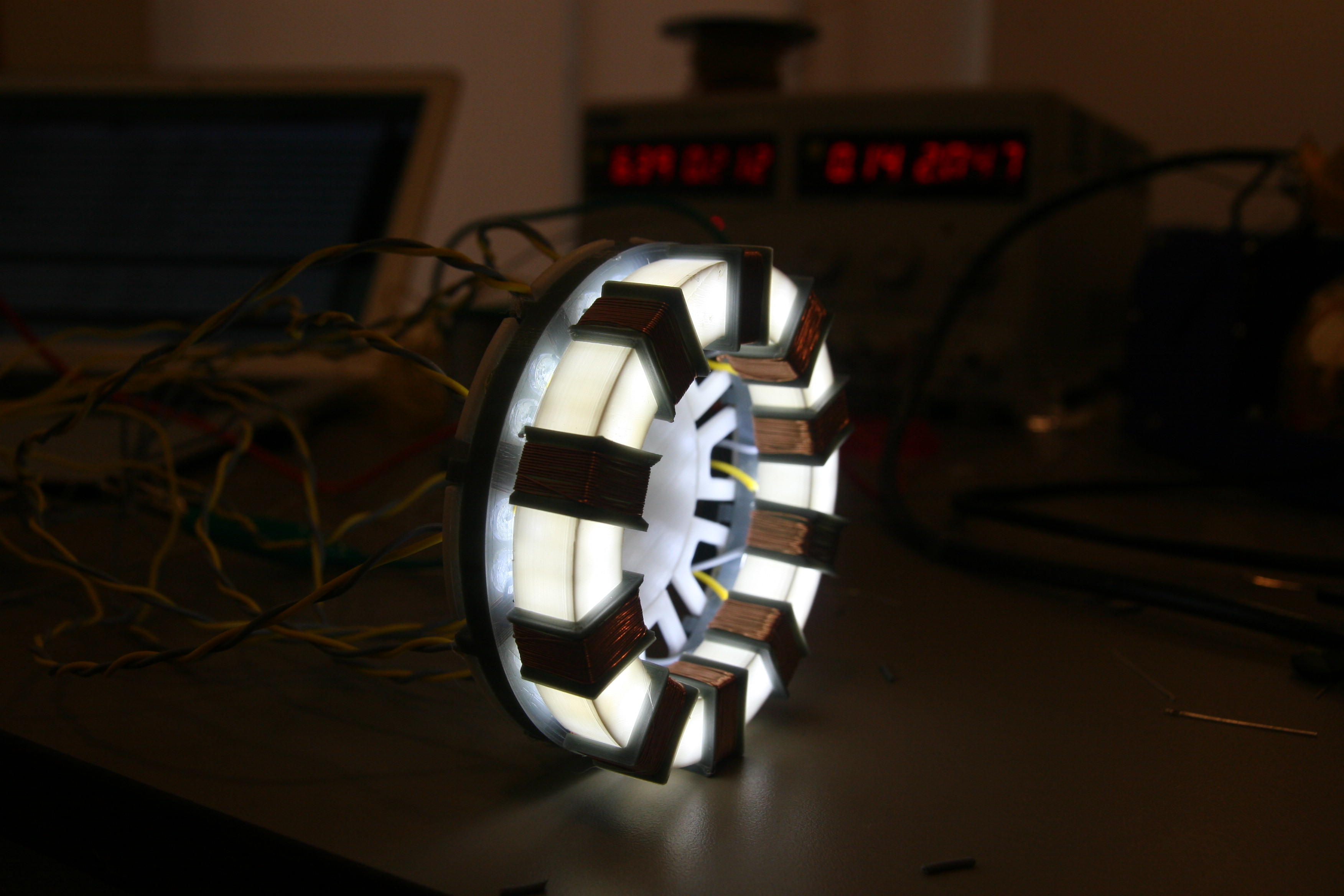
§Step 4: Complete Assembly (and tuck away wires)
The first part went well - all the pieces were glued together, and seemed to work well.
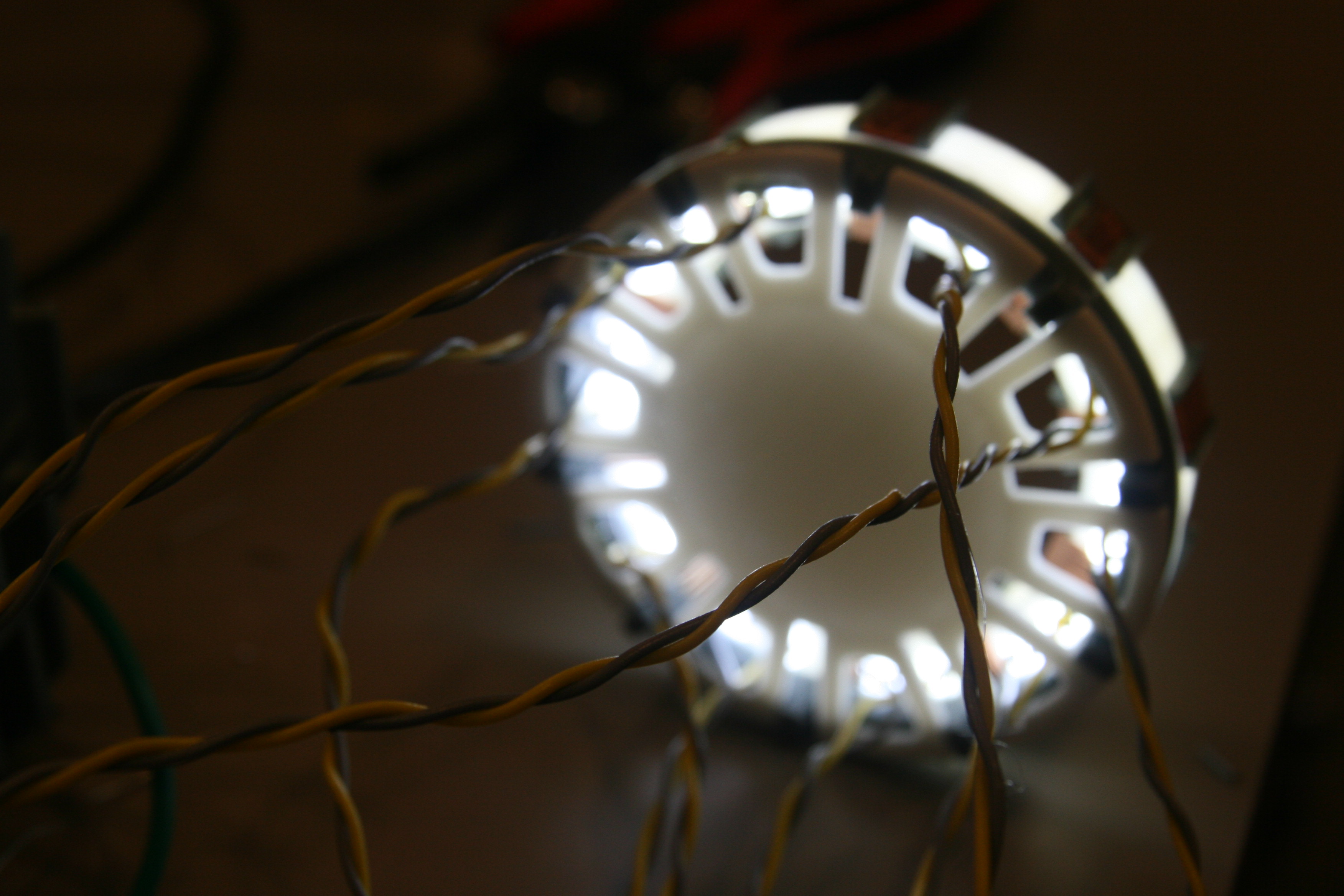
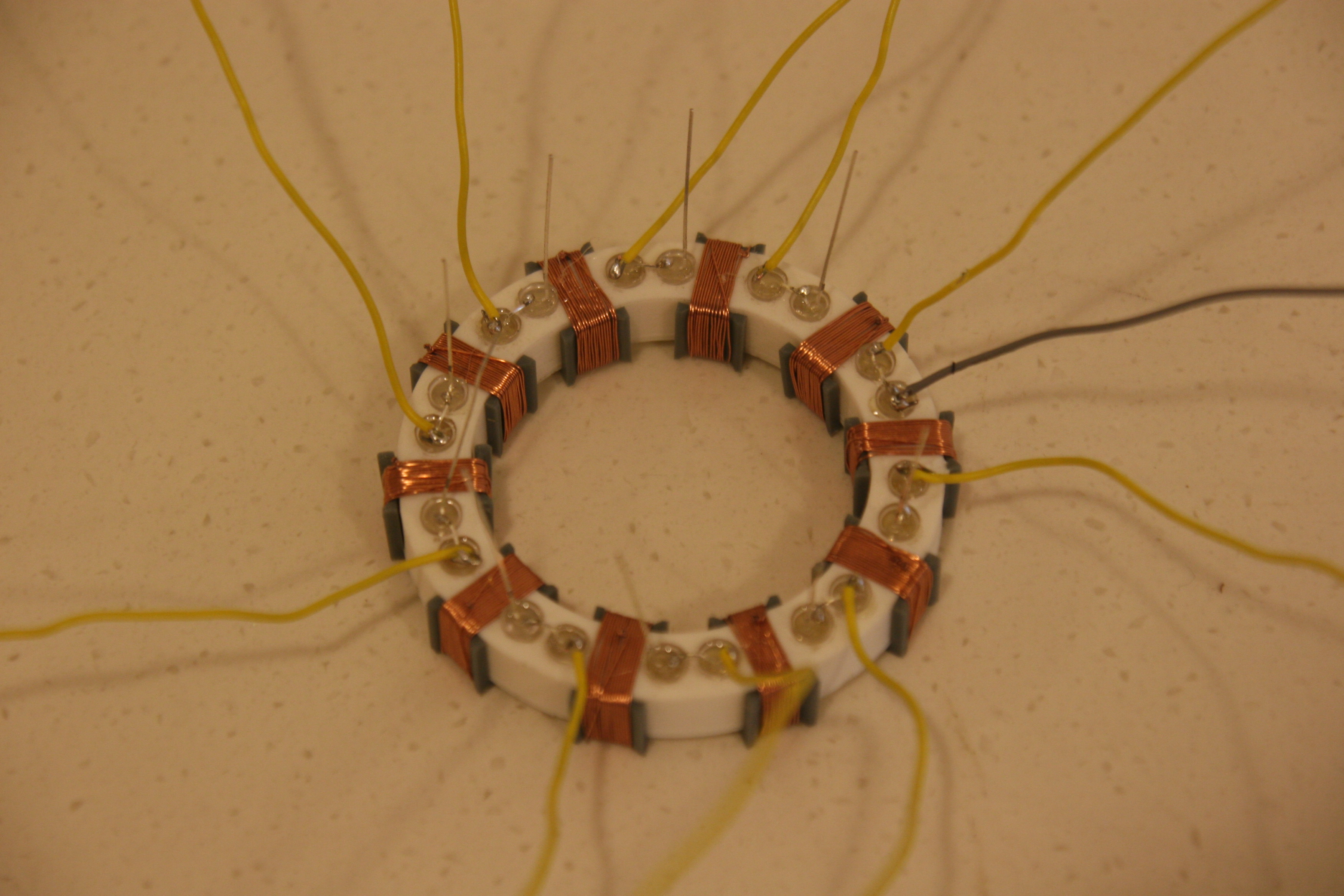
All that remained was to tuck the wires into a position that would be hard to spot. Not very easy - I'd used single-core wire in my haste to make good solder joints. A small note - multi-core wire would be best in this scenario (or in most situations with a need for hidden wires) as they don't resist flexion and can be tucked and glued away pretty easily. In this case, I had to satiate myself with braiding the wires together into one big clump of yellow and white. However, the final product was quite satisfying. Quite a good job, something to be proud of.
Oh, did I not mention that it was too small to be used as a case?

Not a newsletter